 |
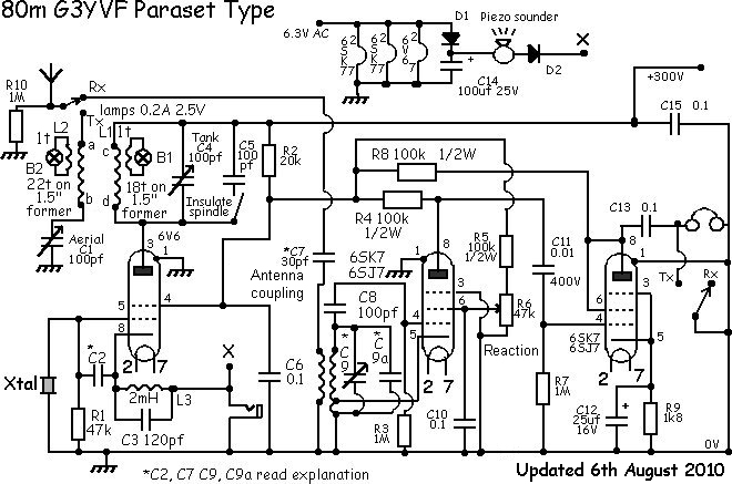
This is the circuit diagram of the
set that will be built.
Explanation
for C2 is here
Explanation
for C7 is here
Explanation
for C9 and 9a is here
|
If
you have not read the "How our Paraset works" section then please have a
look there as many of your questions will be answered !!
|
| 4th August 2010
If you are wanting to make a wood box
version MK7 paraset then start by downloading the files from
here and forward them to
your friendly laser cutters. Check which type of file they need as there
are two sorts available from this web site....either of which they might
be able to use. If you cannot do this contact us and we might be able to
help with the metalwork.
Soft Aluminum does not laser cut with
absolutely perfect edges like steel so you will need to prepare the surface
to make it swarf free and ready to paint if that is your wish. This panel
is left with a natural finish and been scoured with a vibrating mouse sander.
You can see the finish although the photo does not show up the tiny squiggly
circles in the aluminium.
|
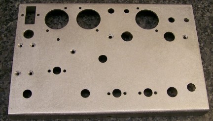 |
| Holes for the available components
have been drilled. Clench nuts have been fitted to take the chassis securing
screws which fix it to the wood box. If you do not have these then use self
tapping screws...but take care not to make the hole too big for your screw
to cut its thread correctly. Always start the self tapping screw precisely
each time you screw it in and never too tightly or you may strip the thread.
Of course you can always tap a thread into the side of the chassis. I had
clench nuts so used these.
Note:- Clench nuts are a nut with a
round portion sticking out. In that round bit it is dished out so that it
can be pushed into a round hole and expanded in a countersink on the other
side of the material. This holds the nut in the material. However to stop
the nut rotating in the material it has a built in "star washer" if you
like..actually a spiky edge to the nut at the round end...this bites into
the material as you expand it in the countersink preventing the nut from
turning when you screw in a screw! |
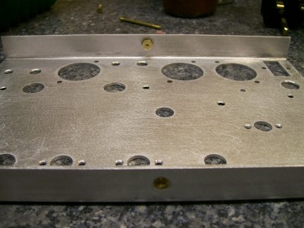 |
| Now is the time to paint the chassis.
If using a Hammerite product then Hammerite on their web site
recommend the use of the "Special Metals Primer" as it promotes
adhesion for metal finish paints on non-rusting metal surfaces such as aluminium.
So follow the instructions for the paint to achieve a good finish.
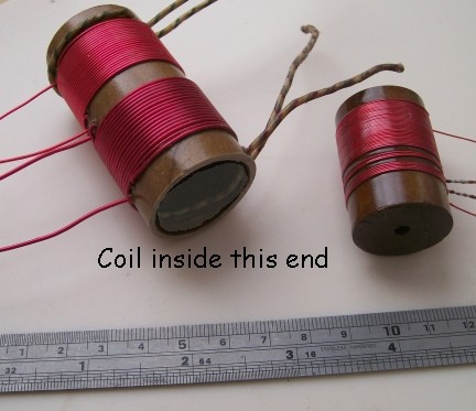
Whilst you are waiting for your paint
on the panel to dry why not make the two coils needed?
The receiver coil, approx 1" dia (not
critical) is wound from the wire to hand, I used 0.4mm. The coil needs to
be fixed to the chassis by a single bolt through the bottom. If your coil
is a tube then fit a wooden stopper in one end and drill a hole through it
for the fixing bolt. This will be fine so long as you do not allow the bolt
to be so long as to be inside the windings. The windings are close wound
and starting from the bottom are 5 turns (the original was 4 but use 5 here)
if the set overloads reduce the coupling capacitor which is easier to do
than remake the coil. See elsewhere
on this site for details. Tap the winding and put on another 3, tap the
winding again and put on 34 or 35 turns. If the tuning range is slightly
too low it is very easy to take one of these 34/35 turns off at a time from
the top of the coil until you get the correct tuning range. But you cannot
put them on if you don't have enough to begin with!! See the photos.
|
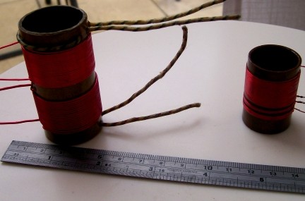 |
| For the tank/antenna coil former I
used the inner from a roll of kitchen foil at approx 1 1/4" dia. This I soaked
in varnish and when dry it made a perfect former. You will notice thicker
wire is used for the tank winding at 18 turns I used 1mm. I wound 22 turns
for the antenna winding of 0.71mm. This wire size makes it look a bit like
the real thing but your winding can use the same wire size. If you use 1mm
wire for both coils you might find it a squeeze to get the coil in as it
will be a bit longer. For some funny reason one of the lamp driver windings
is wound outside the coil and the other inside the coil. Who in their right
mind winds a coil inside the former? What was that about? Was it way of
indicating to the builder which way round the coil goes in the paraset? You
can wind your single turn windings on the outside.....or if you want to follow
this little quirk then look at the photo and follow that example.
|
 |
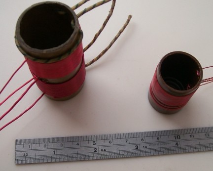
| Varnish the coils well...very well
two or thee coats. If you don't have any varnish dip them in wax.
|
 |
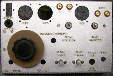
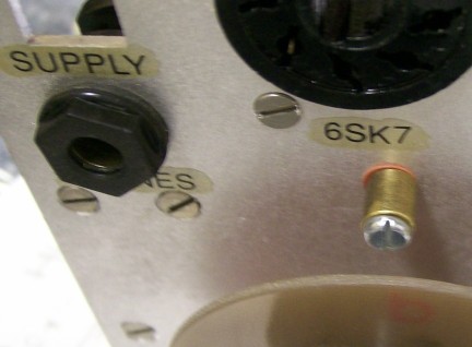
| Now here comes an interesting bit.
MK7 Parasets in a wooden box did not have any lettering on the front panel
to tell the operator what the controls were. So if you wish to follow suit
then do not label the front panel...but make yourself a serial number plate.
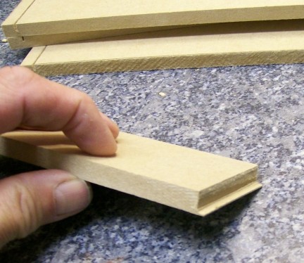
You in the photo of the serial number plates opposite.
This appears to be an aluminium stamping
with the number added after the stamping. The recess is painted black and
it is held in place with rivets probably also aluminium.
The type style is apparently Gill Sans
MT which has also been used in this section.
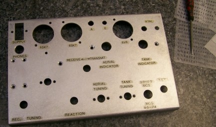
For those of you who like to see some
annotation then get the rub down lettering out and start labeling the controls.
Again look in this web site for help as to what might be needed. I like to
label my creations so out will come the rub down lettering. |
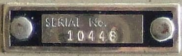
The length of the part we estimate at
38mm and width 11.5mm |
| For those of you who like to see some
annotation then get the rub down lettering out and start labeling the controls.
Again look in this web site for help as to what might be needed. I like to
label my creations so out will come the rub down lettering. |
 |
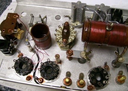
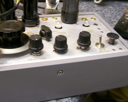
| 6th August 2010
As you can see parts are starting to be
fitted to the front panel. The choke that you can see is not really a choke!!
It is an old transformer that was taken apart and inside a 100k resistor
fitted. Then it was rebuilt to look like and old choke and given lots of
coats of dark brown varnish. The result is something that looks uncannily
like the original choke that was fitted!
|
 |
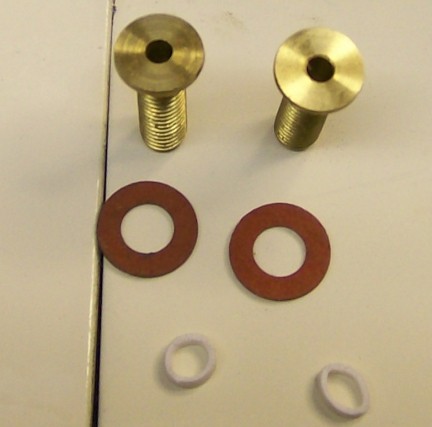
| The antenna, earth and crystal socket
sockets are made from drilling out old brass bolts. They are fitted with
tags underneath of course for the component leads.
|
 |
| Remember, wooden version parasets
(MK7) have never been seen with annotation on the panel. I like to see my
controls inscribed so this paraset is labeled.....but of course when they
were made you had to learn what the controls were for! Don't just look.....get
building!
|
 |
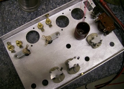
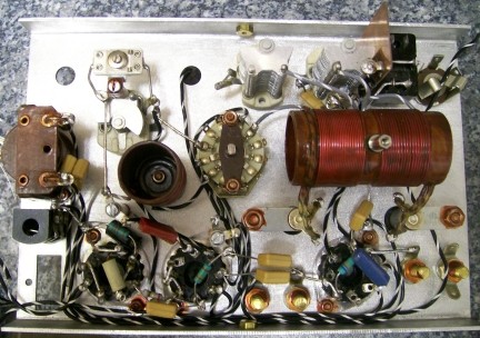
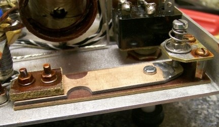
| Here is a photo showing that I am
fitting some parts now. Don't forget to put the earth tags under the securing
screws of the variable capacitors....this is so the shafts can be connected
to earth by the shortest route. Use really thick stout wire for these short
leads as we do not want anything to move and create small changes in capacitance
as we touch the controls....or this will lead to slight changes of receive
frequency as we tune and we do not want that.
You will also see a small "stand off"
fitted onto the tank coil. This it stop the coil touching the work surface
if we turn the chassis over.....so damaging the varnish on the coil. It's
a small thing really...and small things make perfection....perfection however
IS no small thing. So look after your work!
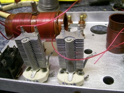
You will notice that I am using 150pF
variable capacitors for the tank and antenna tune. Why not? I had them and
anyway a little more variable capacity here could be handy. What you cannot
see easily is a solder tag sticking out from behind the tank tuning capacitor.
This solder tag is fitted to an insulated stand off fitted to the spare hole
in the ceramic base of the capacitor. This solder tag comes in handy later
as an H.T.+ point to connect one end of the tank coil to. Good eh?
|
 |
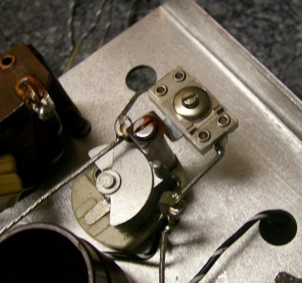
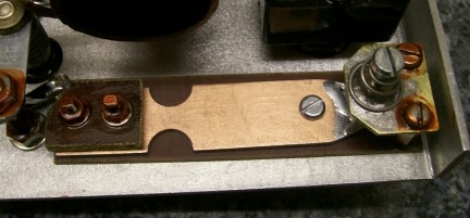
| In my parasets I like to have the
ability to connect and external key without having trailing wires. I do this
by insulating the dial pointer and connecting it to the key jack. Earthing
the pointer now keys the transmitter. Now I can connect an external key with
croc clips...one to the pointer and one to the chassis. Look at the two pictures
and you can see the insulated dial pointer and how the wire is connected
to it under the chassis.
|
 |
| The more astute will also notice the
tuning capacitor is smaller than normal. This is because I am going to bandspread
this paraset to cover only the cw portion of 80m. So a very small tuning
capacitor is needed with some fixed capacity across the tuned circuit. I
want the tuned circuit wires to be very rigid and that is why there is an
extra stand-off near the tuning coil...to support the coil wire and the
connection to the tuning capacitor. Belts and braces comes to mind here.
You will also notice I don't like any
nuts and bolts to come undone....so when installing these I cover the thread
with varnish as I do up the nuts. It does cause problems if of course if
you need to undo the nuts. The answer here is simple: don't make a
mistake! |
 |
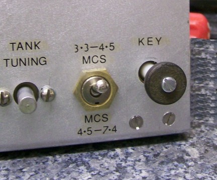
| 7th August 2010
Here you can see most of the components
have been fitted.
|
 |
| One component of interest is the 100pF
ceramic trimmer. This trimmer had a metal bracket as part of the trimmer
so I fitted this to a stand off which I bolted in turn to the tuning capacitor.
As you know this paraset is to be bandspread on 80. This capacitor will allow
me to set 3.5MHz exactly where I want on the dial. All that will need to
be done then is remove plates (both fixed and moving) from the tuning capacitor
until I get the right tuning range. This will done when I have the dial fitted
of course.
Now I will try and make a wooden box
in which to put it.
It would be nice if I found some oak as
the originals seemed to use this wood. I shall start looking for an old chest
of drawers..... |
 |
| 13th August 2010
I have made the morse key for the wooden
version paraset. I used an old FT243 crystal holder as it gave me a piece
of brass for the contact. It also yielded a spring to put under the contact
adjuster. The rest was made from a paxolin scrap piece and the arm from glass
printed circuit board. I keep the arm wider than the original key to make
it rigid as it is pcb material. The two semi-circles are where I filed the
pcb to make it flexible so the arm "hinged" easily. Trial and error is used
here to get it right.
Don't forget to insulate the screws at
the contact end from the arm!
A solder tag is placed against the arm
when it is bolted together and this forms the soldering connection to the
key.
|
 |
| I soldered a nut to the brass contact
part so I could use this thread to "adjust" the gap.
I also soldered a piece of silver strip
across the arm for a key contact...but I don't think this is really needed.
I wouldn't do that again. |
 |
| I haven't made or found a proper knob
for the key yet.....but I will.
It makes a pleasing enough "look alike"
key........ |
 |
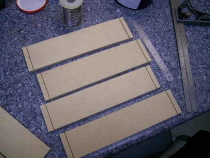
| Here you can see I have cut the pieces
of MDF used for the box. MDF is easy to cut with an ordinary saw. It sands
easily. I glues well and since the originals were painted....grey.....then
it matters not what the box is made from!
|
 |
| As you can see one part of the joint
is a slot the width of one saw cut. Then I cut out a tongue as wide as this
slot using a saw and finishing the joint using a metal file!. MDF files
easily!.
|
 |
| You can see a finished box (bottom
half) with the paraset sitting in this box. Inside on two opposite walls
I glue a small thin strip of wood (balsa) which the paraset chassis sits
on. The chassis is kept in the box by two self tapping screws (or ordinary
machine screws if clinch nuts are fitted to your chassis) which are just
nipped up so as no to strip any thread they cut.
Three coats of British Standard Grey (Dulux
code 3029 00A09) satin wood paint is used...rubbing down between coats. The
result is quite good. You can, using the right primer and spray finishing
coat use any of the special paints like Hammerite if you wish.
|
 |
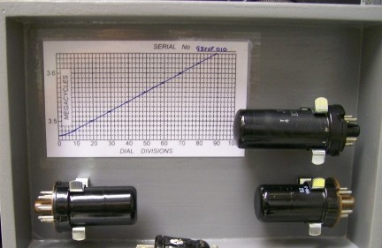
| The dial arrived at last thanks to
a kind offer and so now the paraset has been calibrated.
It was my original intention to try and
use the paraset with its normal receive coverage of roughly 3.3 to 7.4MHz.
But like this the receiver does not give of it best as the L to C ratio of
the receiver tuned circuit is optimised for best performance. Remember I
want to use this little rig and have lots of contacts. The receiver MUST
hold its own on a ham band. Having listened to it there was only going to
be one outcome. It had to be band-spread on 80m and the L to C ratio of the
coil needed to be changed.
If you look at the photo and study the
chart you can see my paraset tunes from 3.47 to 3.64 very nicely. With this
amount of fixed capacity (approx 240pF) the receiver is wonderfully stable
and the reactions slides in and out with barely a change in frequency. I
HAVE MADE IT ! And doesn't it go well on receive. To test the transmitter
I short out the antenna socket to the earth one and key the transmitter.
Both bulbs should light up well if all is ok. All I need now are the correct
knobs for the controls and my paraset a Whaddon MkVII/2 is finished! Well
what are you waiting for!!
If you are patient enough and follow the
instructions you can achieve results like the picture indicates. A nice straight
line tuning characteristic. If you think this is good...then wait till you
try the receiver as the change in LC ratio to achieve this tuning characteristic
makes the reaction easier to use. |
 |
| In the final installment you can see
the finished Whaddon MkVII "paraset".....watch this space.. |
|
|
|
|
|